www.citrelay.com
phone - 763.535.2339 fax - 763.535.2194
page 28
Technical Data
Temperature & Insulation Class
A variety of applications call for relays which can run at higher temperatures typically caused by high ambient temperatures and/or high contact
switching current, which can lead to field failure.
CIT Relay & Switch offers its J107F, J109F, J114AF, J114FL, J115F, J117F and J123F styles with the higher UL class F (155
°
C) rating as standard;
these relays are often used in high temperature applications including HVAC, industrial, spa & pool, automotive and appliance controls. Selection
of the correct insulating system UL Class A, B or F is essential because it separates the coil (control side of the relay) from the switching side
(contacts) of the relay. Maximum ambient temperatures in the application should be considered to determine the correct UL temperature class se-
lection. UL designed specific test proceedures to insure that field breakdown does not occur from agin and heating and has assigned the ratings in
the table below to approve and describe relays falling into specific catagories. CIT Relay & Switch product has been tested by UL and its tempera-
ture class ratings are included in its UL documentation and catalog specifications. The "Hot Spot" temperature noted in the table relates directly to
coil temperature which is a result of the self-heating temperature. At normal room and office temperatures most coils will not exceed 130
°
C under
full contact load and continuous operation. In higher ambient temperatures it is possible that temperatures will exceed this level in which case the
UL F class 155
°
C relay may be the best solution. For extreme temperatures exceeding 155
°
C, contact CIT Relay & Switch for solutions up to 180
°
C.
Maximum Hot Spot Temperatures of Insulating Systems**
System Class*
C
°
*Figures derived from UL document 1446
A
105
** Insulation System - Defined as the combination of insulating
materials used in the relay coil inclusive of magnet wire coating
and the outer wrapping of the relay coil
B
130
F
155
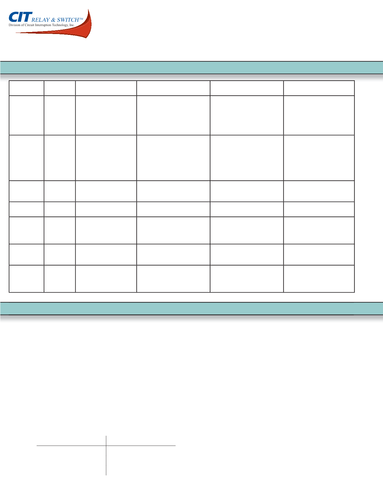
Contact
Material
Chemical
Composition
Typical Loads
Recommended
Advantages
Disadvantages
Notes
Gold
Au
Dry Circuit
< 0.4VA
No corrosion forms
Low electrical noise
Poor resistance to metal transfer
with loads greater than 1/2A
Gold clad is often used to block
the polymer buildup. Where gold
plating is used CIT recommends
15 micro inch over a nickle base or
standard silver rivet. All CIT relay
contacts can be gold plated
Silver Paladium AgPd
1 milliamp @ 1 Volt min,
5A maximum
Resistant to sulfidation
Resistant to oxidation
Good contact wear
Good resistance to metal transfer
Low electrical noise level
Life expectancy of 10 times that of
fine silver
Expensive
Low electrical conductivity
Poly buildup in dry circuit condition
Contacts should be bifurcated to
ensure make
Has yet to prove cost effective.
Fine Silver
Ag
10 milliamp @5 Volt min,
10A maximum
High electrical conductivity
High thermal conductivity
Resistant to oxidation
Sulfidation easily forms
Easily welds at higher current levels
High electrical noise
Silver Nickel
AgNi10
10 milliamp @5 Volt min,
40A maximum
Good contact wear
Good resistance to welding
Higher contact resistance
90% Silver, 10% Nickel
Silver Cadmium
Oxide
AgCdO
10 milliamp @5 Volt min,
40A maximum
Good contact wear
Good resistance to welding
Superior resistance to metal loss &
transfer
Environmental concerns
Higher contact resistance
Sulfidation easily forms
Relay manufacturers are phasing
out this material due to RoHS
requirements
Silver Tin Oxide AgSnO
2
100 milliamp @5 Volt min,
50A maximum
High Thermal conductivity
Excellent resistance to welding
High contact resistance
Low electrical conductivity
Sulfidation easily forms
CIT standardizaed contact of choice
Silver Tin Oxide
Idium Oxide
AgSnO
2
In
2
O
2
100 milliamp @5 Volt min,
50A maximum
High thermal conductivity
Excellent resistance to welding
Used with very high inrush loads
High melting point
High contact resistance
Low electrical conductivity
Contact wear
Solfidation easily forms
CIT contact for very severe inrush
loads
Contact Material Review


