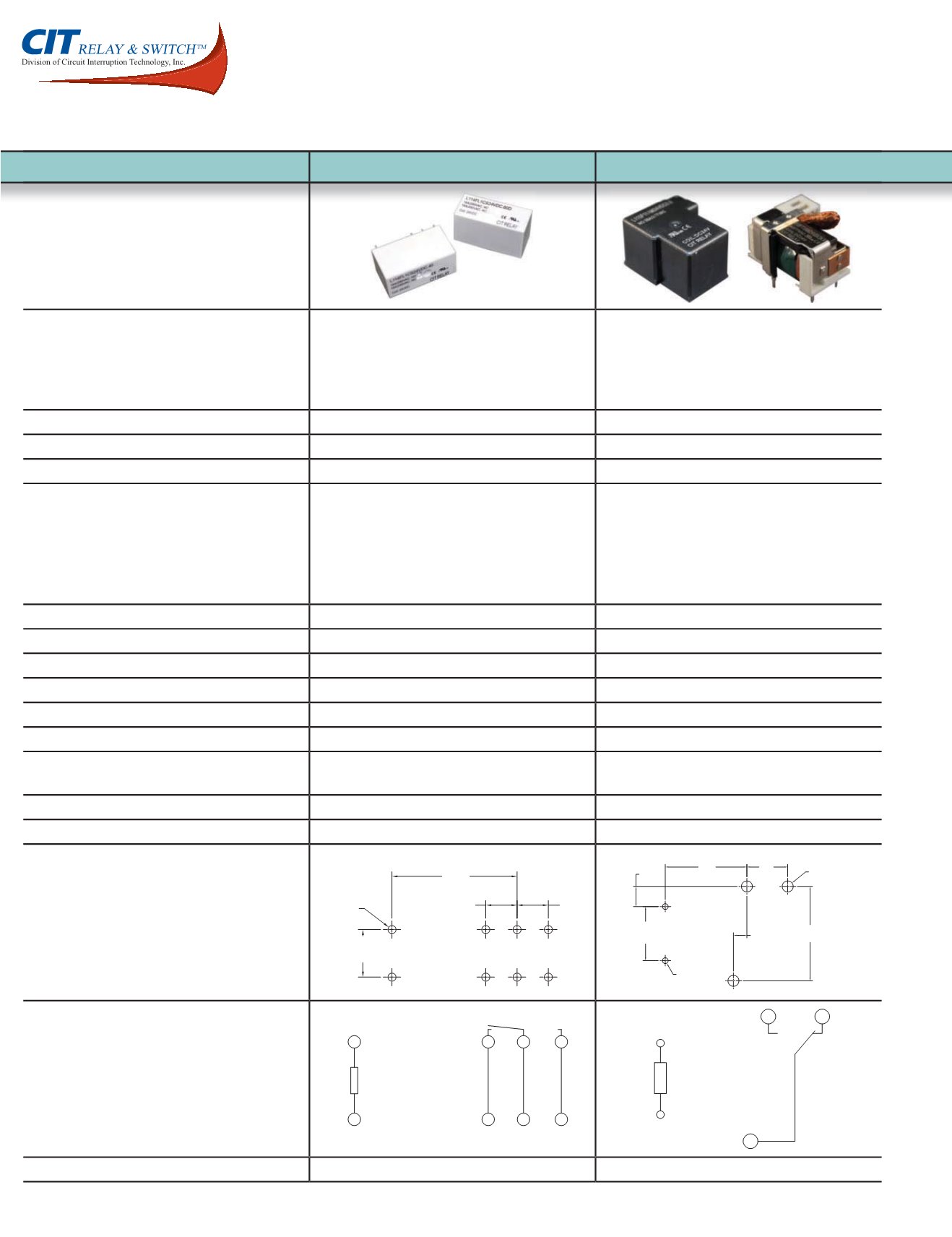
Dimensions shown in mm. Dimensions are shown for reference purposes only.
Speci cations and availability subject to change without notice.
Latching Relays
Series Number
L114FL
L115F1
Appearance
Features
Single Coil or Double Coil Latching
Creepage Distance 8.4mm
Heavy Contact Load
Strong Shock & Vibration Resistance
UL / cUL Certified
Single Coil Latching
UL F Class Rated Standard
Heavy Contact Load
Strong Shock & Vibration Resistance
UL / cUL Certified
Dimensions (L x W x H mm)
29.24 x 13.15 x 15.7
26.9 x 31.7 x 20.3
Contact Arrangement
1A, 1C
1A, 1B, 1C
Contact Material
AgSnO 2, AgSnO 2 In 2 O
AgSnO 2, AgSnO 2 In 2 O
Contact Ratings
NO : 16A @ 240VAC Resistive; 50k cycles; 85
°
C ambient
NC : 16A @ 240VAC Resistive; 50k cycles; 85
°
C ambient
NO : 30A @ 277VAC Resistive; 6k cycles; 25
°
C ambient
NO :
40A @ 277VAC Resistive; 6k cycles; 25
°
C ambient
NO :
50A @ 277VAC Resistive; 6k cycles; 25
°
C ambient
NC : 30A @ 277VAC Resistive; 6k cycles; 25
°
C ambient
NC :
40A @ 277VAC Resistive; 6k cycles; 25
°
C ambient
NC :
50A @ 277VAC Resistive; 6k cycles; 25
°
C ambient
Coil Voltage Options
3 ~ 24VDC
5 ~ 48VDC
Coil Power Options
.40W & .60W
.90W & 1.50W
Contact Resistance
< 50m
< 50m
Insulation Resistance
1000
@ 500VDC
100M
@ 500VDC
Electrical Life
50K cycles
50K cycles
Mechanical Life
500M cycles
1M cycles
Dielectric Strength Contact to Contact
Contact to Coil
1000V rms
5000V rms
1500V rms
2500V rms
Operating Temperature
-40
°
C to 85
°
C
-55
°
C to 125
°
C
Mounting Methods
PC Pin
PC Pin
PC Board Layouts
20.00
[.79]
5.00
[.20]
5.00
[.20]
7.60
[.30]
8X Ø1.30
[.05]
7.70
[.30]
17.80
[.70]
(3X) Ø 2.10
[.08]
3.80
[.15]
10.20
[.40]
(2X) Ø 1.10
[.04]
15.40
[.61]
2.54
[.10]
Schematics
1
2
4 7 3
9 6 8
S R
+
+
-
-
+ -
- +
S R
Agency Approvals
E197851
E197852
page 20
www.citrelay.com
phone - 763.535.2339 fax - 763.535.2194


